RTS-X User Manual — Main Screen
Overview
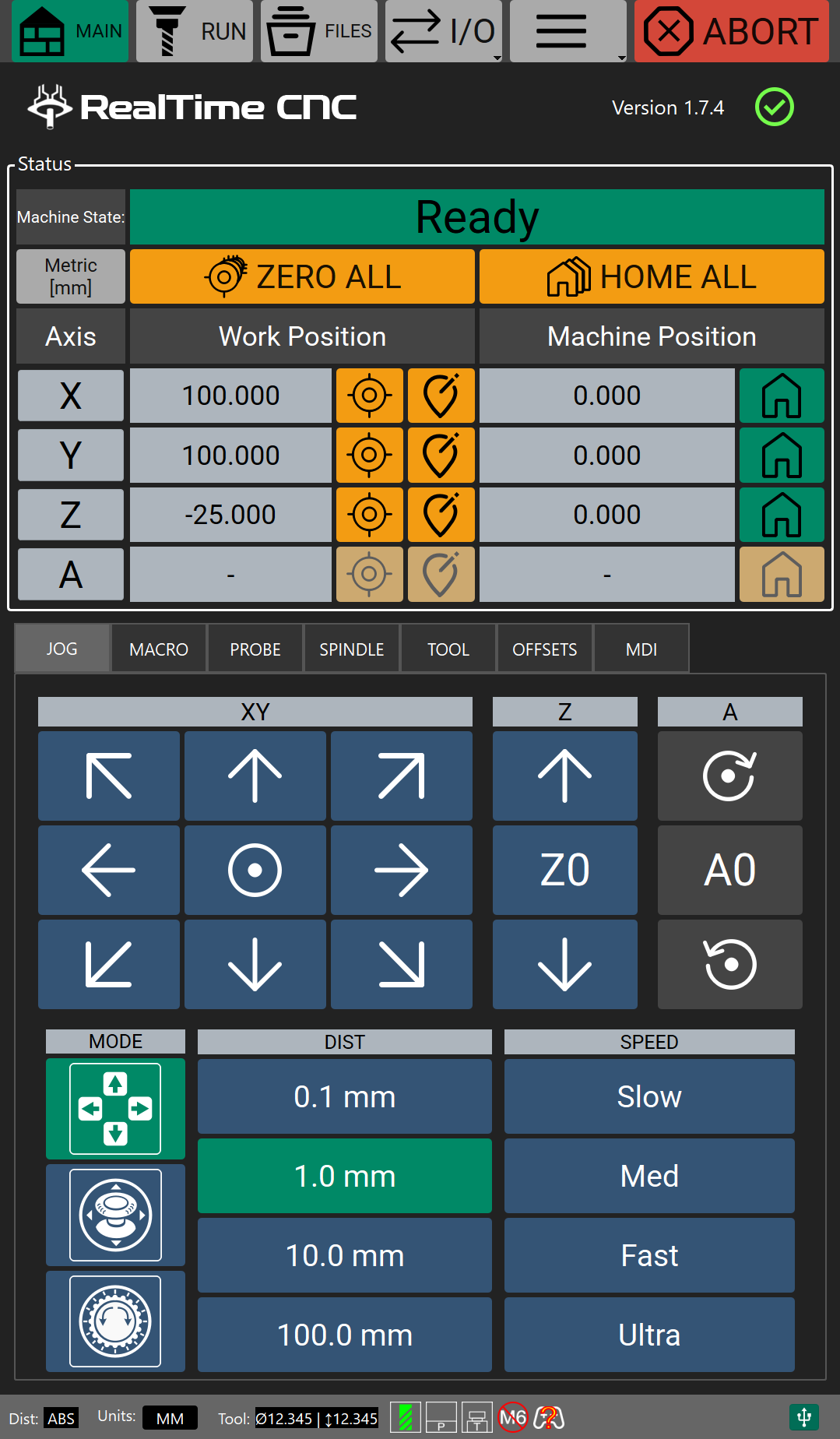
The Main screen is the home screen of RTS-X software, and the screen you land on when the application starts. It gives you at-a-glance machine status, manual axis control (jogging), probing, spindle/laser control, tool management, work offset management, and quick access to macros, general-purpose I/O, and the MDI (Manual Data Input) console.

The Main screen is reached at any time by pressing the MAIN button in the navigation sidebar (landscape/desktop displays) or toolbar (portrait/touchscreen displays).
The layout adapts to the orientation of your display:
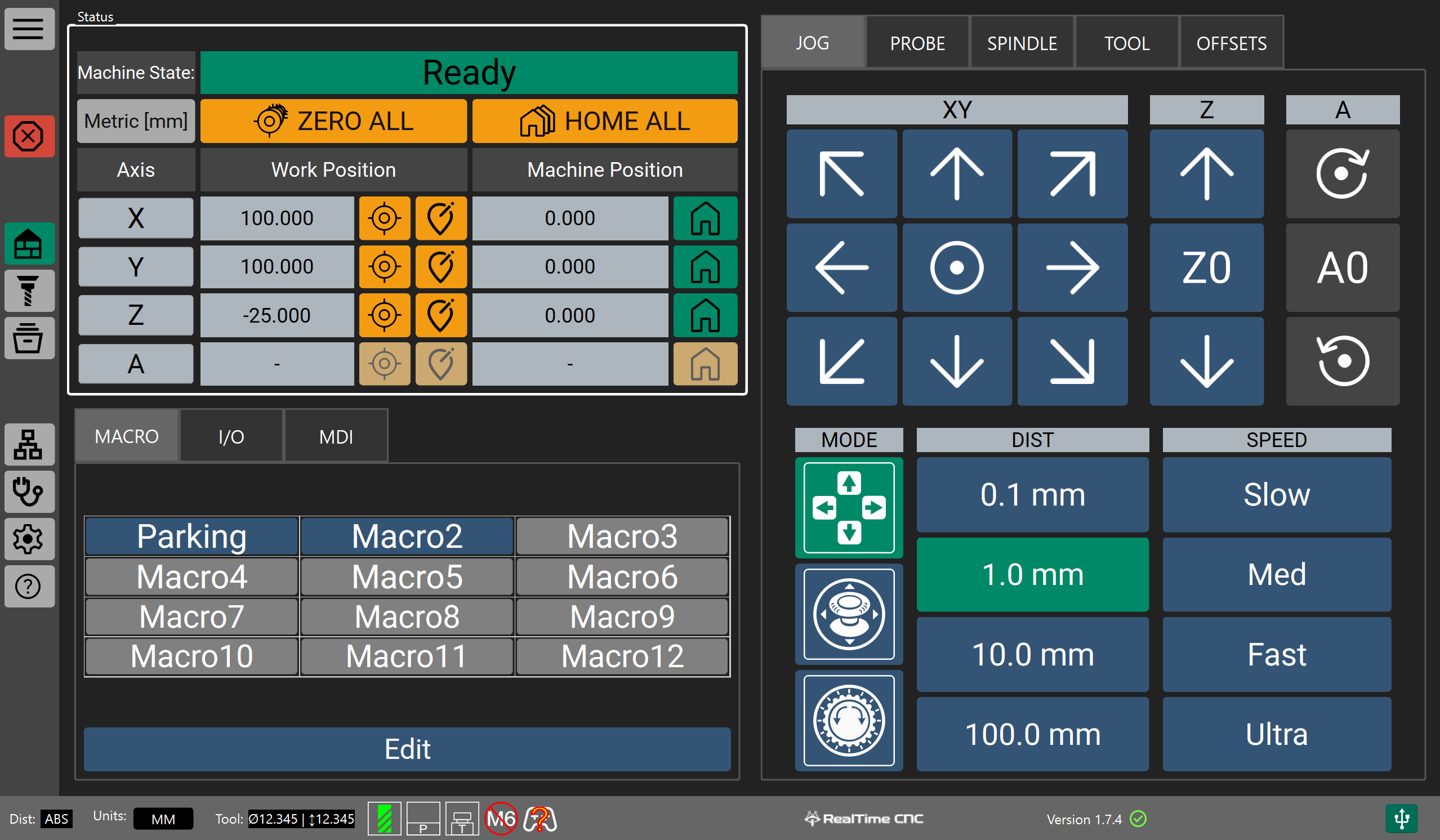
- Landscape (typical desktop monitor): a left column with the Status panel above the Shortcut Panel (Macro / I/O / MDI tabs), and a right column with the tabbed Accessory Panel (Jog / Probe / Spindle / Tool / Offsets).
- Portrait (touchscreen HMI): a top banner, followed by the Status panel, followed by the Accessory Panel, which in this orientation also absorbs the Macro and MDI tabs (since output toggles are already available from the toolbar's I/O menu).
Regardless of orientation, a Status Bar is always visible along the bottom of the window. In portrait mode a toolbar is always visible along the top. In landscape mode, the navigation sidebar is always visible along the side.
Most controls on the Main screen are only enabled while the machine is Idle. This is a safety measure — axis zeroing, homing, jogging, probing, and offset edits are disabled while a program is running or the machine is in an alarm/error state.
Summary Table
| Control Group | Purpose |
|---|---|
| Navigation Sidebar / Toolbar | App-wide navigation, Abort, quick I/O, Remote/Update/Diag/Config/Help |
| Banner | RTCNC logo, software version and update indicator (portrait only) |
| Status Panel | Machine state, per-axis DRO, zero/home/motor-reset |
| Jog Tab | Manual XY/Z/A jogging, distance & speed presets, go-to-origin |
| Probe Tab | Guided block and rotary probing routines |
| Spindle/PWM Tab | Spindle or laser on/off, direction, target RPM/power |
| Tool Tab | Tool setter measurement, tool change, tool table |
| Offsets Tab | Work coordinate system (WCS) management |
| MDI Tab | Manual command console with history |
| Macro Tab | 12-slot quick-run G-code macros |
| I/O Tab | General-purpose output toggles |
| Status Bar | Persistent machine telemetry, always visible |
Navigation Sidebar / Toolbar
The sidebar/toolbar is visible from every screen in the application. It is used to navigate between screens and trigger a few important global actions.
The button for the screen you're currently viewing is highlighted.
| Control | Description | |
|---|---|---|
| Toggle/Hide |  |
Expands or collapses the sidebar (landscape only) to save screen space. |
| ABORT |  |
Immediately requests that the current operation/motion aborts. Flashes a warning color while pressed. |
| MAIN | |
Navigates to the Main screen (this screen). |
| RUN |  |
Navigates to the Run screen, used for streaming and monitoring a loaded G-code program. |
| FILES |  |
Navigates to the File Manager screen, used to browse and load G-code files. |
| WEB / Remote |  |
Opens a dialog showing a QR code and IP address for connecting to the machine's web-based remote interface from another device. |
| DIAG |  |
Navigates to the Diagnostics screen (hardware status, logs, changelog, licenses). |
| CONFIG |  |
Navigates to the Settings screen. |
| HELP |  |
Navigates to the Help/Manual screen. |
| I/O menu (portrait toolbar only) |
 |
Flyout with 4 toggle buttons for the general-purpose outputs (same function as the I/O panel described below). |
| UPDATE (portrait toolbar menu only) |
 |
Opens the software update dialog. |
Banner (portrait orientation only)
A section shown at the top of the screen in portrait/touchscreen layouts.
| Control | Description | |
|---|---|---|
| Logo |  |
RTS-X logo. Not interactive. |
| Version indicator |  |
See Version / Update Indicator below. |
Version / Update Indicator
Shown in the Banner (portrait) or in the Status Bar (landscape).
| Control | Description |
|---|---|
| Version label | Displays the currently installed software version in the format MAJOR.MINOR.PATCH. |
| Update status icon | Indicates software update status. Spins while checking for a software update in the background, then shows a green check (up to date), a warning icon (check failed), or an update-available icon. Clicking it when an update is available on the desktop verison of the software offers to open the RealTimeCNC download page. |
Status Panel (Digital Readout)
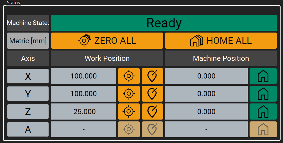
The Status group box is the primary digital readout (DRO) for the machine — it shows machine state and the position of every axis, and provides zeroing/homing controls.
| Control | Description |
|---|---|
| Machine State | Text readout of the current machine state (e.g. Idle, Run, Alarm, Dwell with countdown, E-Stop, Offline). Flashes for warning states such as E-Stop or a motor error. |
| Units toggle | Switches the displayed units between Metric (mm) and Imperial (in). This affects readouts throughout the application and sets the units to be interpreted by the controller. |
| ZERO ALL | Zeroes the work position of every axis at once (may prompt for confirmation, depending on settings). |
| HOME ALL | Homes every axis. Checks for any faulted axis first and shows an error if homing can't proceed. |
For each axis (X, Y, Z, and A — which is relabeled V when a linear fourth axis is configured instead of a rotary one):
| Control | Description |
|---|---|
| Axis letter button | Clears ("resets") a motor fault on that axis (RTS-2 controller only). Turns red/warning-colored when that axis currently has a motor error. |
| Work Position readout | The axis position in the active work coordinate system (accounts for the work offset, and for the tool length offset on Z). Shows "?" if the axis hasn't been homed. |
| Zero (small icon button) | Zeroes the work position of just that axis. |
| Set Position (small icon button) | Opens a numeric entry dialog to manually type a specific work-coordinate value for that axis. |
| Machine Position readout | The axis position in raw machine coordinates (no work offset applied). |
| Home (small icon button) | Homes just that axis. Turns green once homed, orange/warning if not yet homed. |
All Status Panel controls are disabled unless the machine state is Idle.
Accessory Panel
A tabbed control group containing the bulk of the Main screen's functionality: Jog, Probe, Spindle (labeled PWM in laser mode), Tool, Offsets, and — in portrait layouts only — Macro and MDI. A hidden DEV tab can be unlocked via the version label trick described above.
Jog Tab
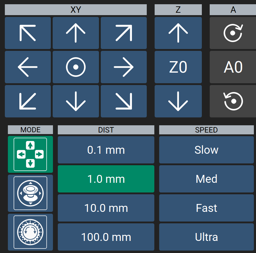
Manual axis-motion control.
| Control | Description |
|---|---|
| XY jog pad | An 8-direction arrow pad for moving X and Y. In "speed" mode, holding a direction jogs continuously; in "distance" mode, each press moves by the selected step distance. Motion is clamped to the configured axis travel limits. |
| Origin button (center of XY pad) | Opens the XY origin sub-page (see below). |
| Z jog buttons (Up/Down) | Jogs the Z axis up or down. |
| Z0 button | Opens the Z origin sub-page (see below). |
| A/V jog buttons (CW/CCW) | Jogs the fourth axis. Icons switch between rotary (CW/CCW) and linear (arrows) depending on configuration. |
| A0/V0 button | Opens the Z origin sub-page (see below). |
| Mode selector | Switches the jog input method between Digital (on-screen buttons), Analog (an on-screen joystick for XY plus sliders for Z/A — suited to gamepad-style continuous jogging), and Dial (for an on-screen MPG/handwheel pendant). |
| DIST selector | Chooses the step distance used for distance-mode jogging, from four presets (tiny/small/medium/large), shown with the active unit suffix. |
| SPEED selector | Chooses the continuous jog speed, from four presets (Slow/Medium/Fast/Ultra). |
XY Origin sub-page (opened from the ⌂ button):
| Control | Description |
|---|---|
| Machine Zero (MPOS X0Y0) | Rapids to machine-coordinate X0, Y0. Prompts for confirmation and performs a Z-height safety check first. |
| Work Zero (WPOS X0Y0) | Rapids to work-coordinate X0, Y0. |
| Cancel | Returns to the jog pad without moving. |
Z Origin sub-page (opened from the Z0 button):
| Control | Description |
|---|---|
| Machine Zero (MPOS Z0) | Rapids Z to the machine-coordinate zero. |
| Work Zero (WPOS Z0) | Rapids Z to the work-coordinate zero. |
| Cancel | Returns to the jog pad without moving. |
A/V Origin sub-page (opened from the Z0 button):
| Control | Description |
|---|---|
| Machine Zero (MPOS A0) | Rapids A to the machine-coordinate zero. |
| Work Zero (WPOS A0) | Rapids A to the work-coordinate zero. |
| Cancel | Returns to the jog pad without moving. |
Probe Tab
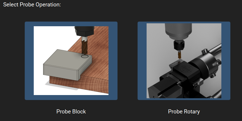
Guided probing routines using a calibration/probe block, plus rotary probing when a fourth axis is enabled.
| Control | Description |
|---|---|
| Probe Block | Opens the probe block workflow: a clickable diagram lets you pick which corner, or center-Z zone to probe, with an animated preview of the probing motion. Back and Start Probing buttons confirm or cancel. |
| Probe Rotary (only shown if a rotary axis is enabled) | Opens the rotary probing workflow, with Probe Rotary Z and Probe Rotary XYZ options. |
Probing controls are only enabled while the machine is Idle.
Spindle / PWM Tab
Spindle or laser control. Which sub-page is shown depends on how the spindle output is configured in Settings.
- Disabled mode — informational only; spindle commands in G-code are ignored.
- Manual mode — informational only; you'll be prompted to turn the spindle on/off by hand when a program calls for it.
- Output ON/OFF mode — a single toggle button (labeled with the configured output name) that switches a general-purpose output on or off for external spindle control.
- VFD mode (for VFD-type spindle drives):
| Control | Description |
|---|---|
| ACTUAL / TARGET RPM | Live readouts of current and commanded spindle speed. |
| TORQUE bar | Color-graded (green→yellow→red) load indicator. |
| Warmup button | Starts a spindle warm-up routine (only while Idle). |
| Numeric keypad | Type a target RPM directly. |
| Speed dial | Set target RPM (0–24000) by rotating a dial. |
| REV / OFF / FWD | Set spindle direction to reverse, off, or forward. |
- Laser (PWM) mode:
| Control | Description |
|---|---|
| TARGET % | Readout of commanded laser power. |
| Power dial | Sets laser power as a percentage (0–100%, capped by the configured maximum). |
| OFF / ON | Toggles the laser output. The ON button highlights red while active. |
Tool Tab
Sub-tabs for tool setter measurement, tool changes, and the tool table.
Tool Setter sub-tab:
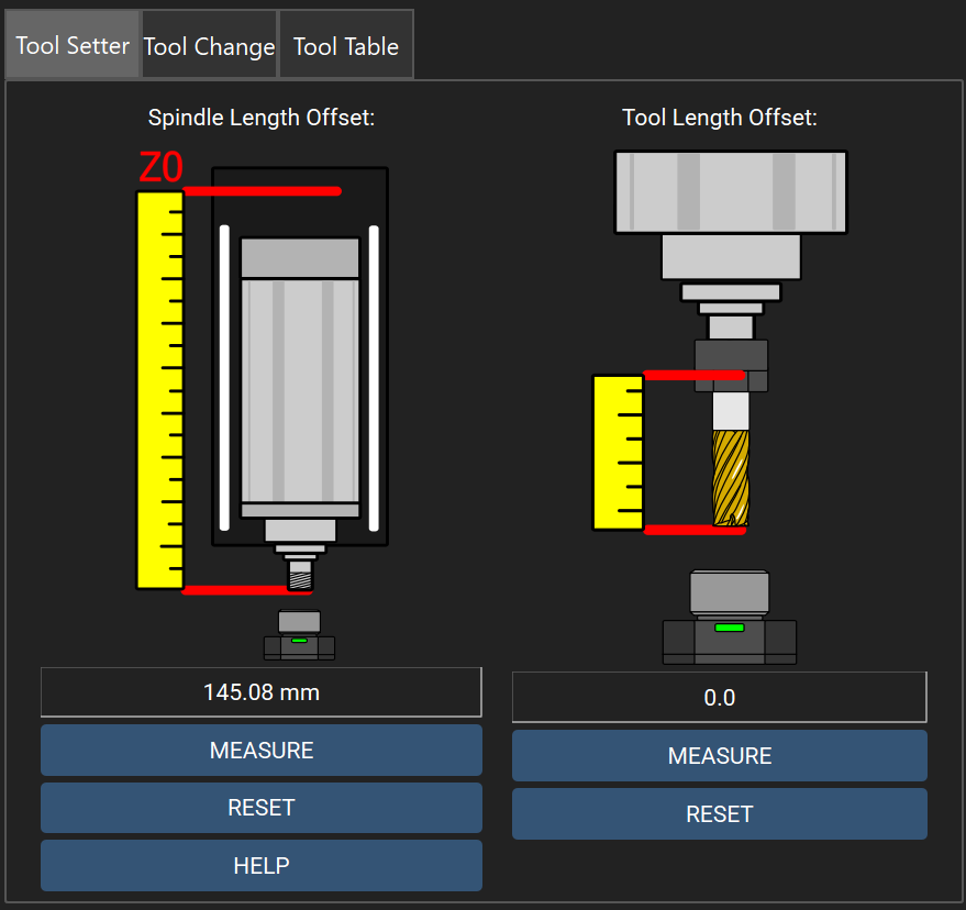
For more information on spindle and tool length offsets click here.
| Control | Description |
|---|---|
| Spindle Length Offset — MEASURE | Runs an automatic measurement of the spindle-to-Z0 reference offset. Requires the machine to be homed and Idle; prompts for confirmation since it resets the tool offset. |
| Spindle Length Offset — RESET | Clears the measured spindle reference offset. |
| HELP | Explains what the spindle reference measurement means. |
| Tool Length Offset — MEASURE | Automatically measures the current tool's length offset using the tool setter. |
| Tool Length Offset — RESET | Sets the current tool's length offset to zero. |
Tool Change sub-tab:
-
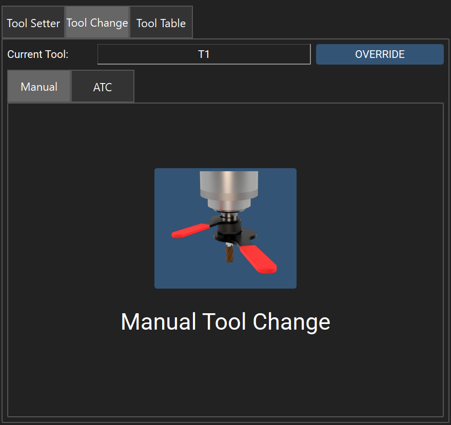
Manual Tool Change
-
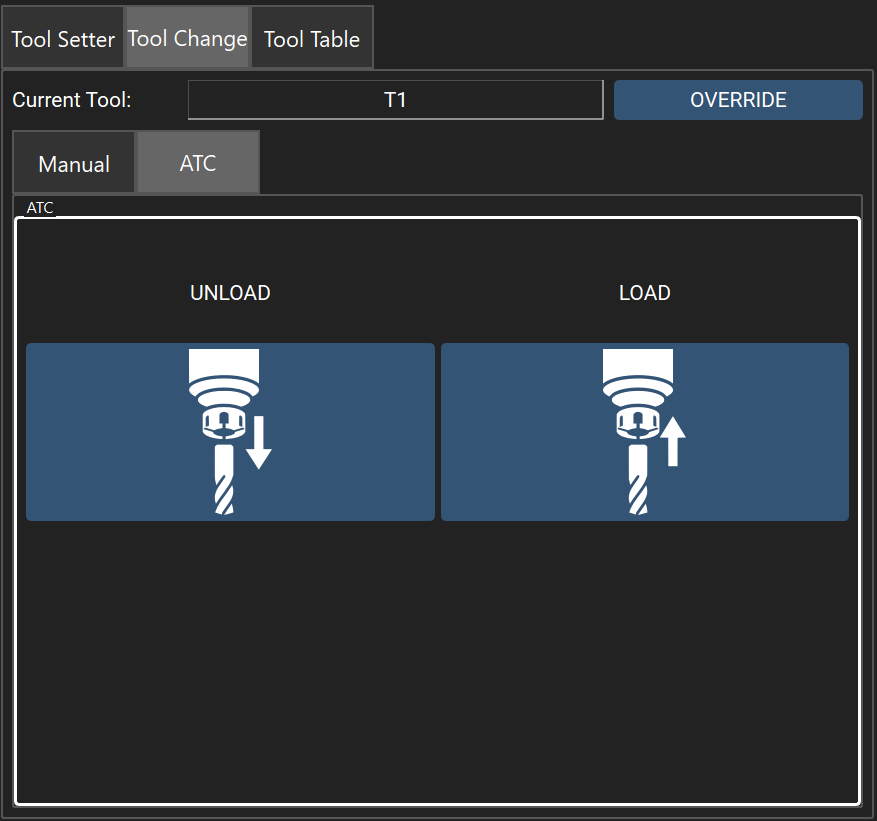
ATC Tool Change
| Control | Description |
|---|---|
| Current Tool readout | Shows the tracked current tool number. |
| OVERRIDE | Manually overrides the tracked tool number (opens a numeric entry dialog) without physically changing tools. |
| Manual Tool Change | Prompts for the new tool number, warns about the rapid motion involved, and runs the manual tool-change sequence. |
| LOAD / UNLOAD (ATC only, shown only if an automatic tool changer is configured) | Runs the automated tool pickup/dropoff sequence. |
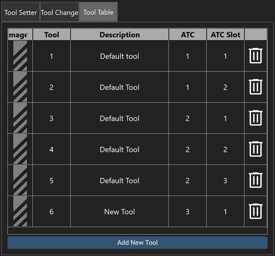
Tool Table sub-tab: a spreadsheet-style table of all tool numbers with their diameters and length offsets.
Offsets Tab
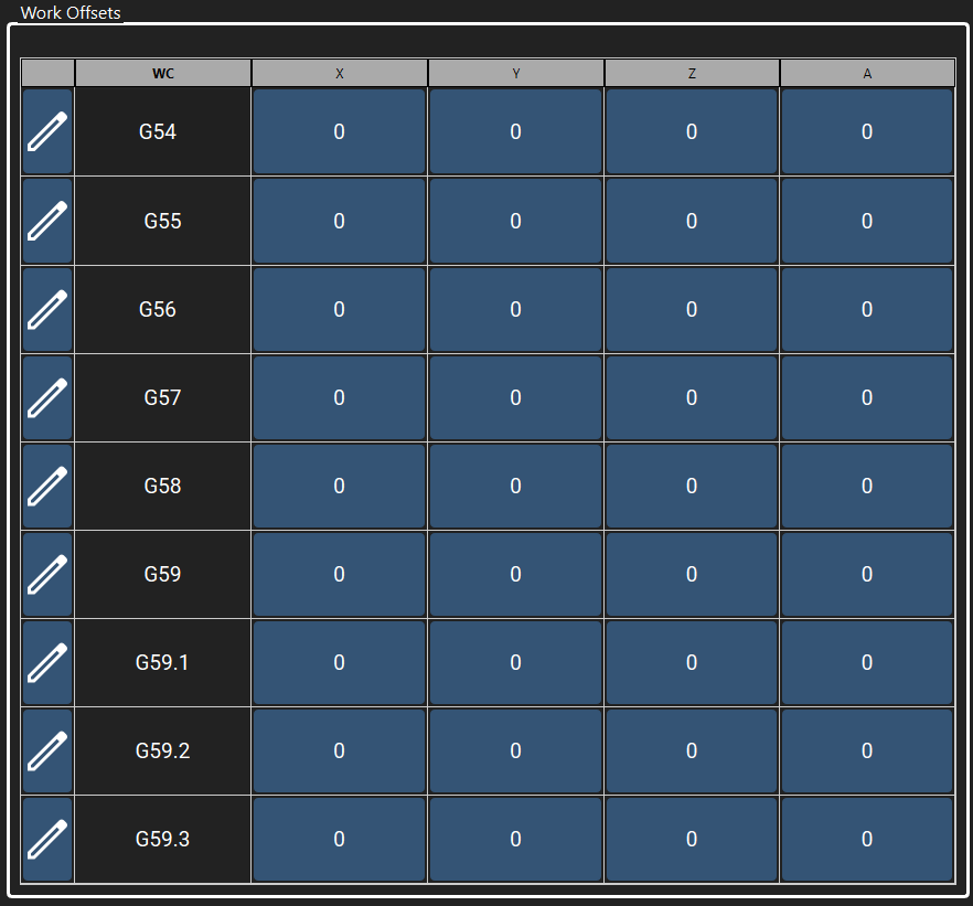
Manages the machine's Work Coordinate Systems (WCS: G54–G59.3).
| Control | Description |
|---|---|
| Edit-name (pencil icon) | Renames the selected WCS (e.g. to "Fixture 1"). |
| WC cell (e.g. "G54") | Activates that coordinate system (prompts for confirmation). |
| X / Y / Z / A cells | Click any axis-offset cell to open a numeric entry dialog and set that axis's offset for the corresponding WCS. Values respect the current unit setting. |
There are 9 WCS rows in total (G54 through G59.3), and the table refreshes automatically whenever offsets change.
MDI Tab
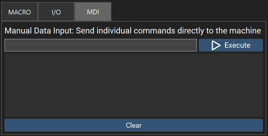
Manual Data Input — a console for sending raw G-code/M-code commands directly to the machine. Present on the Accessory Panel in portrait layouts, or on the Shortcut Panel in landscape layouts.
| Control | Description |
|---|---|
| Command entry field | Type a command; press Enter or the Execute button to send it. Disabled unless the machine is Idle. |
| On-screen keyboard (portrait only) | Touch-friendly keyboard for entering commands. |
| History list | Shows the most recently executed commands. Click an entry to reload it into the command field. |
| Clear | Empties the command history list. |
Shortcut Panel (landscape orientation only)
A tabbed group in the left column, below the Status Panel, holding the Macro, I/O, and MDI tabs. (In portrait layouts these are folded into the Accessory Panel / toolbar instead.)
Macro Tab
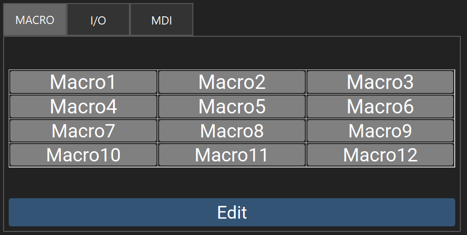
Twelve quick-run G-code macro slots, arranged in a 3×4 grid.
| Control | Description |
|---|---|
| Macro button (grid cell) | Runs the assigned G-code file, if the machine is Idle and a file is assigned. Color indicates state: gray = unassigned, blue = assigned, red = assigned file is missing. |
| Edit | Opens the macro editor, where each of the 12 slots can be renamed, assigned a G-code file, or cleared. |
I/O Tab
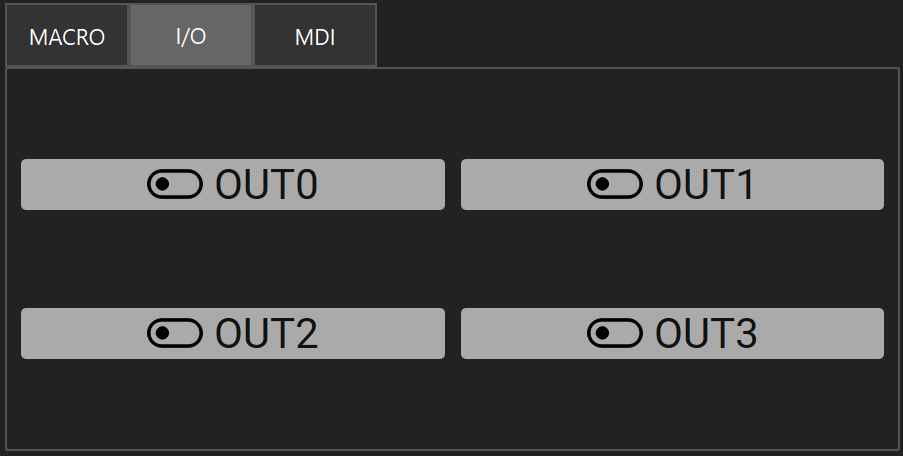
Direct control of the machine's 4 general-purpose outputs.
| Control | Description |
|---|---|
| Output toggle buttons (×4) | Each button, labeled from the configured output name, turns that output on or off. Highlights when active. |
MDI Tab
Same functionality as the MDI tab described under the Accessory Panel above.
Status Bar
Persistent strip along the bottom of the window, visible on every screen (not just Main).

| Item | Description |
|---|---|
| Dist | Current distance mode (Absolute/Incremental). |
| Units | MM/IN readout — click to toggle units. |
| Tool | Current tool number, diameter, and length offset. |
| Spindle icon | Spindle (or laser) on/off indicator. |
| Probe icon | Indicates when the probe is triggered. |
| Tool Setter icon | Indicates when the tool setter is triggered. |
| Toolchange icon | Shows the configured tool-change mode (disabled/manual/ATC). |
| Gamepad icon | Shows whether a gamepad is connected. |
| Pendant icon | Shows whether an MPG pendant is connected. |
| Network icon (Raspberry Pi builds only) | Wi-Fi/Ethernet connection status. |
| Logo + Version widget (landscape only) | Same as the Banner's version indicator. |
| Connection icon | Serial connection status, flashes green when connected |
| Power menu (Raspberry Pi builds only) | Flyout with RESTART (relaunches the application), REBOOT, and SHUTDOWN, each with a confirmation prompt. |