Emergency Stop
An Emergency Stop or E-Stop, is the most critical component of any CNC system. Its primary purpose is to protect the operator and the machine by providing a reliable, immediate method to halt all motion in the event of a malfunction, user error, crash, or safety breach.
E-Stop disconnects are typically prominent, red mushroom-head style buttons designed for fail-safe operation. They are mounted in easily-accessible locations and are designed for high visibility.
In a properly configured CNC system, the E-Stop should immediately stop all motion and ensure the safety of the workspace.
Software vs Hardware E-Stop
PHYSICAL LOCKOUTS REQUIRED
 ALWAYS ensure that proper safety barriers and lockouts to prevent physical injury are installed on your CNC machine.
 NEVER rely on software or firmware for safety.
ALWAYS have physical emergency stop (e-stop) mechanisms on your CNC machine
ALWAYS have separate emergency stop (e-stop) mechanisms/circuits for spindles.
ALWAYS adhere to laser safety precautions and regulations when using laser systems. Lasers can blind and burn you instantly.
In most CNC controllers, including the RTS-X series, the software will include STOP, ABORT or E-STOP buttons in software. It is important to note that these controls should never be relied on for safety-critical functions.
Safety is a hardware requirement, not a software feature
Connecting an E-Stop to the RTS-X Controllers
The RTS-X controllers are designed to operate with external E-Stop circuits. The E-Stop circuitry implementation is left to the machine builder. Safety and E-Stop requirements vary from machine-to-machine and region-to-region.
SAFETY STANDARDS & CERTIFICATIONS
ALWAYS consult and follow safety standards pertaining to your CNC machine and region. Different parts of the world have different safety requirements when it comes to CNC machines and safety disconnects.
CNC systems integrating RTS-X motion controllers should be independently reviewed and certified as required by your local code requirements.
Basic Implementation
An example of a basic e-stop implementation is show below. The e-stop is wired in series with the motor power supply to ensure that all power to the axis motors is cut when the e-stop is activated.
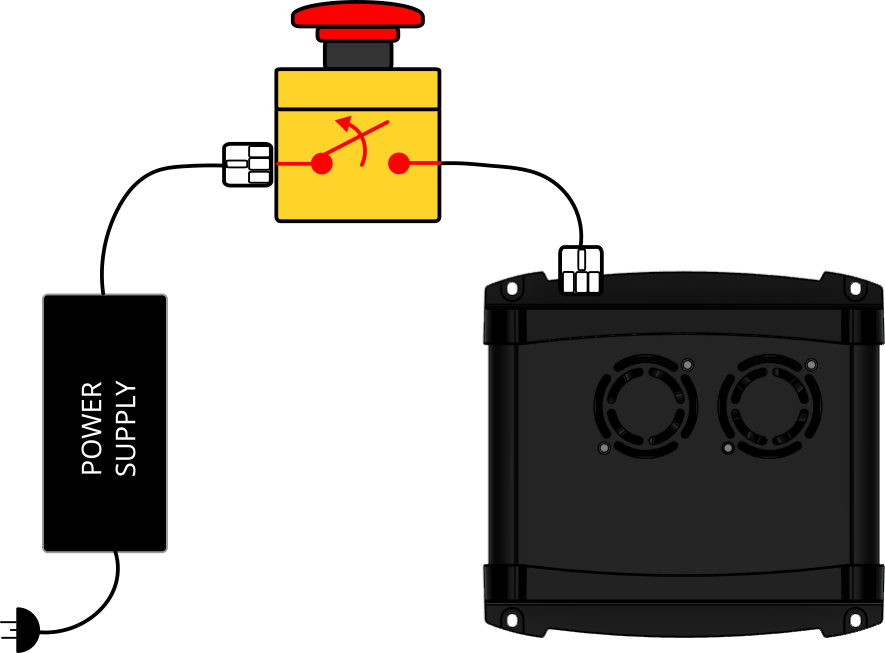
The actual wiring implementation will depend on the CNC machine safety requirements and applicable machine safety standards.
The RTS-X controllers will recognize a loss in motor input voltage and display the E-Stop condition in software until the motor voltage is restored by resetting the E-Stop mechanism.
E-Stop Examples
-
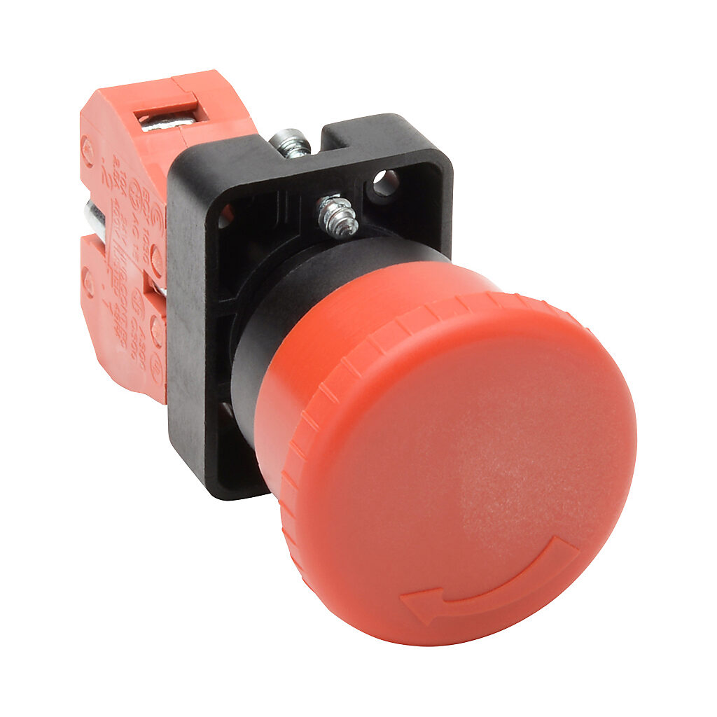
Standard E-Stop
-
E-Stop with Keylock
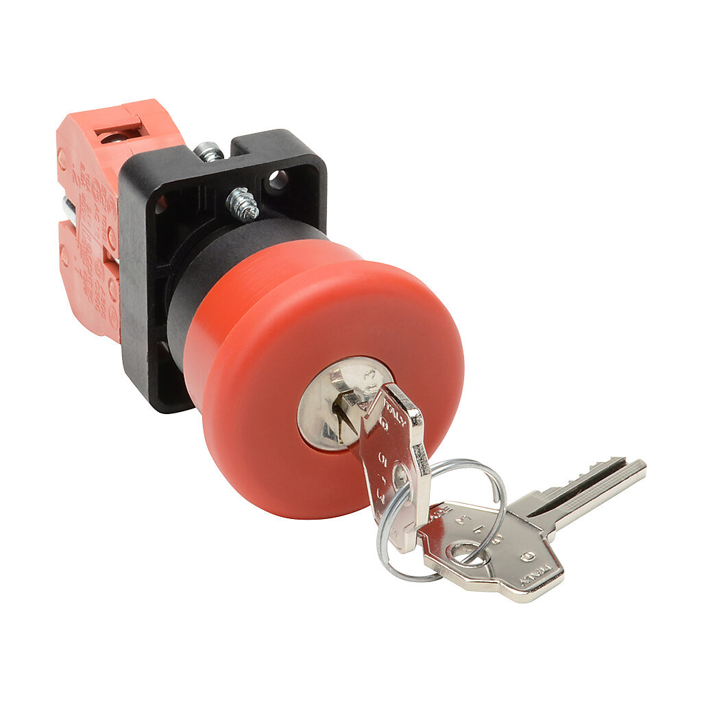
E-Stop pushbutton assemblies are typically modular and allow for different switch contact blocks to be mounted on the switch assembly. The switch blocks can be normally-open or normally-closed depending on the application and downstream electrical loads. Most common E-Stop switches allow multiple switch blocks to be attached so multiple loads can be switched simultaneously.
SAFETY STANDARDS & CERTIFICATIONS
Always consult the applicable safety standards and verify agency compliance and certifications when selecting an E-Stop.
Not all E-Stop switches meet international standards such as CE, CSA and UL. Be wary of cheap or inexpensive safety equipment.
Connecting Spindles & Lasers
The RTS-X series of controllers support multiple types of spindles and lasers. These peripherals should have their own dedicated safety disconnect mechanism. In some cases, power disconnect for these devices can be achieved using the same E-Stop pushbutton as the CNC motor power supply by adding additional switch blocks to the E-Stop.
Consult the documentation for your spindle and laser and follow all safety requirements. Also review our safety precautions and warnings.