Settings
All software and hardware configuration settings are accessed from the CONFIG screen of the software.
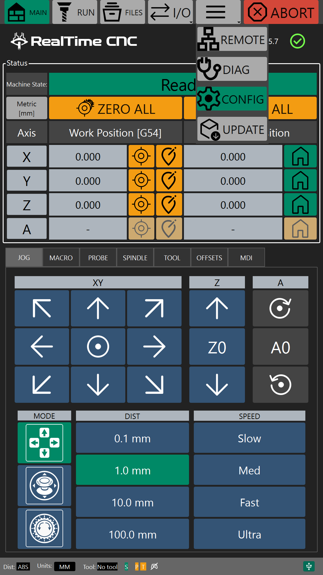
In portrait mode, the CONFIG screen is accessed through the "hamburger" drop down menu.
In landscape mode, the CONFIG screen is accessed by clicking on the gear icon on the left side of the screen.
General Settings
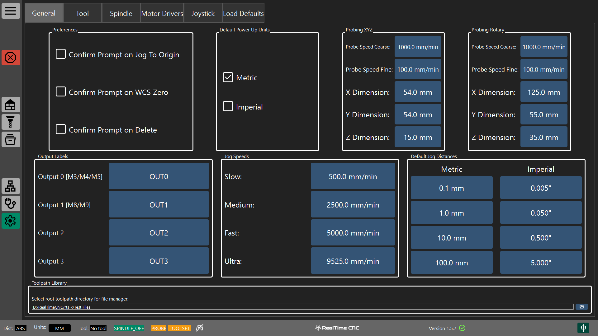
The general settings screen allows the user to customize the software behavior.
Preferences
The preference group controls when the software displays certain prompts.
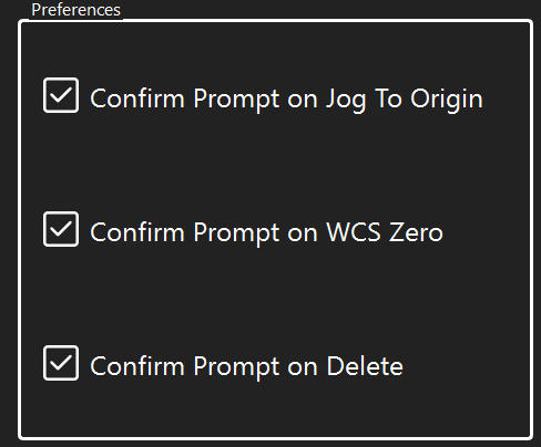
Jog to Origin Prompt
When checked, the software will display a confirmation box when the jog to origin jog buttons are used.


This prompt can be useful as a safety check to ensure the user confirms the path to the origin is clear before moving the tool head.
WCS Zero Prompt
When checked, the software will display a confirmation box when the WCS offsets are zeroed.


This prompt can be useful to ensure that the user intends to zero the work coordinate offsets for the current WCS.
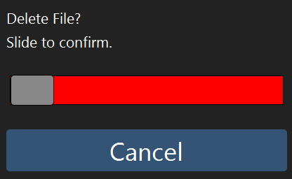
Confirm Delete Prompt
When checked, the software will display a confirmation box when a file is deleted in the file manager.
Default Power Up Units
These settings control the preferred startup units of the controller.
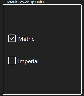
Note
This control only sets the preference for metric or imperial when the controller first starts up.
Some tool paths may call for different units using G20 or G21 which will switch the controller to the requested units.
Probing XYZ
This control group contains the probe settings for a rectangular probing block used to probe X, Y and Z starting coordinates.
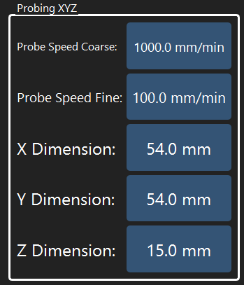
The Probe Speed Coarse and Probe Speed Fine settings control how fast the tool head will approach the probe block during the probe operation.
The coarse speed generally a faster speed so the probe tool can find the probe block quickly.
Once the probe tool has touched the probe block, it will back off slightly and then search toward the probe block again at the fine probing speed. This ensures that the final touch-off with the probe block is executed accurately.
The X, Y, and Z dimensions represent the offsets from the probing edges of probe block and the zero point of the probe block.
Note
It is highly recommended to measure the X, Y and Z values accurately with digital calipers to ensure the best accuracy when using a probe block.
Probing XYZ
This control group contains the probe settings for a rotary probing block used to probe X, Y and Z starting coordinates.
Typically, the probe block is attached to the rotary axis with known X, Y, and Z offsets to the desired work origin of the rotary axis.
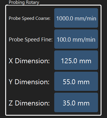
The Probe Speed Coarse and Probe Speed Fine settings control how fast the tool head will approach the probe block during the probe operation.
The coarse speed generally a faster speed so the probe tool can find the probe block quickly.
Once the probe tool has touched the probe block, it will back off slightly and then search toward the probe block again at the fine probing speed. This ensures that the final touch-off with the probe block is executed accurately.
The X, Y, and Z dimensions represent the offsets from the probing edges of probe block and the zero point of the rotary axis.
Note
It is highly recommended to measure the X, Y and Z values accurately with digital calipers or refer to the rotary axis specifications to ensure the best accuracy when using a probe block.
Output Labels
This control group contains allows the user to customize the output control labels.
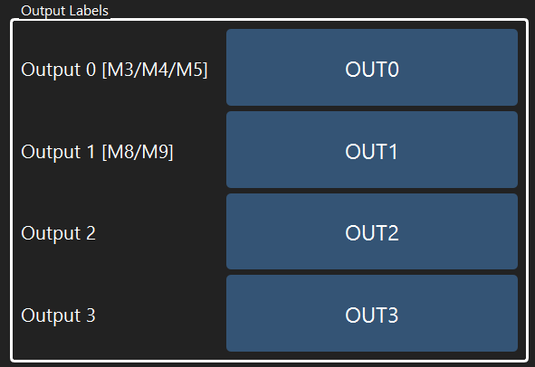
Click on an output name to rename it.
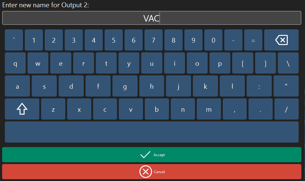
Note
It is often helpful to rename outputs to match any connected accessories. For example, renaming an output to VAC or DUST for dust collection systems or MIST for a coolant system.
Jog Preferences
The Jog Speeds and Jog Distances groups allow customization of the machine's jogging behavior.
Jog Speeds
Use the Slow, Medium, Fast, and Ultra settings to adjust the target speeds for continuous jogging.
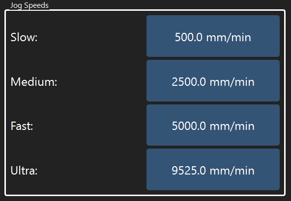
Note
The jog speed settings apply to continuous jogging using the on-screen arrow keys, the on-screen analog sticks, or an attached gamepad.
Jog Distance
Use the jog distance settings to adjust the distance increments for distance jogging.
Separate values can be entered for metric and imperial units.
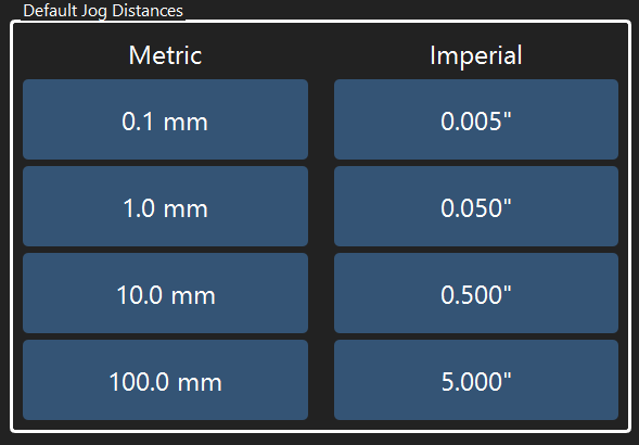
Note
The jog speed settings apply to distance jogging using the on-screen arrow keys or the on-screen pendant.
Tool Settings
The tool settings screen allows the user to adjust tool change behavior.
General Settings
The General settings tab contains the preferences and settings for controlling tool change behavior, tool setter parameters, and manual tool change parameters.
Tool Change Mode
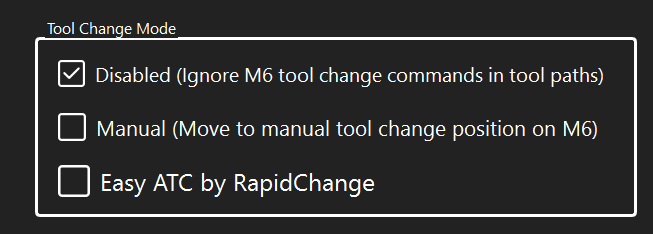
The Tool Change Mode setting group controls how the controller responds to tool change commands in toolpaths.
When checked, all tool change commands (M6) in a toolpath will be ignored.
The controller will skip over the tool change command and continue with the g-code command.
When checked, the controller will execute a manual tool change when for each M6 g-code.
A tool setter is required for manual tool changes as the controller will measure and calculate the tool length offset after each tool change.
The manual tool change position can be set in the manual tool change position setting group.
When checked, the controller will execute an automatic tool change using a RapidChange Easy ATC for each M6 g-code.
A tool setter is required for manual tool changes as the controller will measure and calculate the tool length offset after each tool change.
The Easy ATC can be set up and configured on the Easy ATC tab of the Tool settings.
Tool Setter
The Tool Setter setting group sets the position and probing speeds for a tool setter.
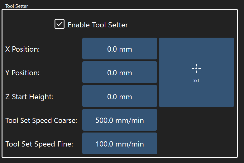
Check the Enable Tool Setter box to enable the tool setter.
This will enable manual length offset measurements via the TOOL tab on the main screen of the software and automatic tool length offset measurements during tool changes.
The X and Y position values set the center position (in absolute machine coordinates) of the tool setter. These values should be set such that the tool is over the exact center of the tool setter.
The Z Start Height is the absolute Z position where the controller will start probing the length of the tool.
Warning
 Ensure that the Z Start Height is high enough to account for the longest tool that will be measured.
Failure to set the Z Start Height high enough can damage the tool, the machine and/or the tool setter.
The Tool Set Speeds control how the machine approaches and touches the tool setter.
The coarse speed is the initial plunge speed of the tool to the tool setter.
The fine speed is used after the first touch-off of the tool setter. The machine will back off slightly and approach the tool setter again at the fine speed to verify and calculate the tool length offset.
Note
This is often referred to as the "double-tap" method of tool length measurement. The machine finds the approximate length of the tool at a faster (coarse) speed and then verifies the final measurement at a slower speed.
The Set button can be used to launch the tool setter setup wizard. This wizard will guide you through setting the tool setter parameters.
Manual Tool Change Position
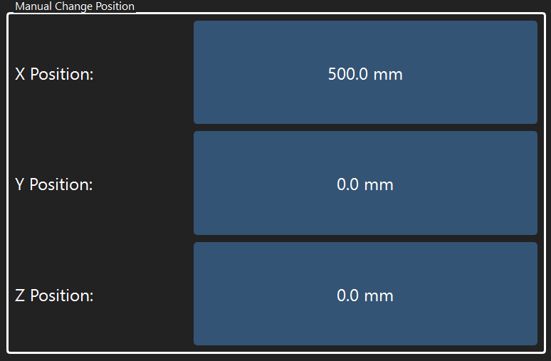
The Manual Tool Change position is the absolute X, Y and Z coordinates that the machine will travel to for a manual tool change operation.
In the example above, the machine will move to X=500 Y=0 Z=0 whenever a manual tool change is initiated.
Note
It is often convenient to set the manual tool change position near the front of the machine for easy access to the spindle when changing tools.
Easy ATC
The Easy ATC settings tab contains the preferences and settings for Easy ATC tool magazines.
ATC Location
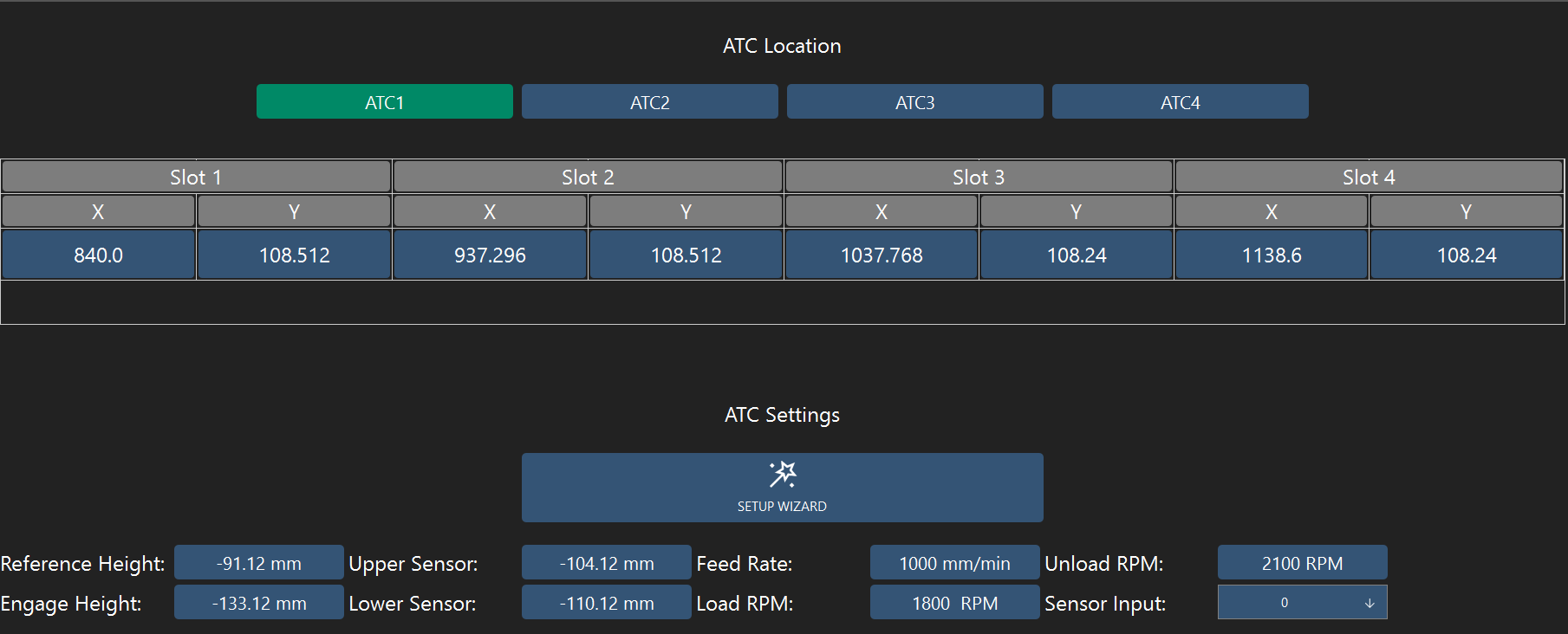
The four buttons marked ATC1, ATC2, ATC3 and ATC4 select the active ATC magazine for configuration. Up to four Easy ATC magazines are supported for a total of 16 tool slots.
The coordinate table holds the X and Y coordinates for each ATC tool slot. These can be set manually or using the ATC setup wizard (recommended).
ATC Settings
Setup Wizard
The Easy ATC setup wizard can be launched by clicking on the SETUP WIZARD button.
This wizard is designed to guide you through the process of setting up and testing an Easy ATC magazine.
ATC Parameters
The table below summarizes the parameters and settings for an Easy ATC magazine.
| Parameter | Description |
|---|---|
| Reference Height | Z height of the top plane of the ATC magazine. |
| Lower Sensor | Z height used to detect the collet nut when loading and unloading the tool. Refer to Sensor Heights |
| Upper Sensor | Z height used to detect the collet nut when loading and unloading the tool. Refer to Sensor Heights |
| Engage Height | Z height used to plunge and engage the collet nut tightening mechanism |
| Feed Rate | Plunge speed when loading and unloading the tool |
| Load RPM | Spindle speed when loading a tool |
| Unload RPM | Spindle speed when unloading a tool |
| Sensor Input | Selects input [0-7] for infrared beam sensor |
| Third Strike on Tool Load | Enable for an extra plunge into the ATC collet nut tightening system when loading tools |
Sensor Heights
The Easy ATC utilizes an infrared beam sensor to detect the presence and absence of the spindle collet nut when changing tools.
When unloading a tool, the machine will first retract to the Lower Sensor height and check the sensor to make sure the collet nut is not present. It will then retract to the Upper Sensor height and check the sensor again to ensure the nut is not present.
When loading a tool, the machine will first retract to the Lower Sensor height and check that the collet nut is present. This indicates that the collet nut has been threaded on to the spindle.
The machine will then retract to the Upper Sensor height and check the sensor to make sure the collet nut is seated properly. If no collet nut is detected, the nut is correctly threaded such that it clears the sensor beam. If the collet nut is detected at this height, it is likely cross-threaded and sitting too low on the spindle. The machine will abort the tool change if a cross-threaded condition is detected.
Spindle Settings
The spindle tab contains settings for selecting a spindle and configuring the PWM output.
Spindle Selection
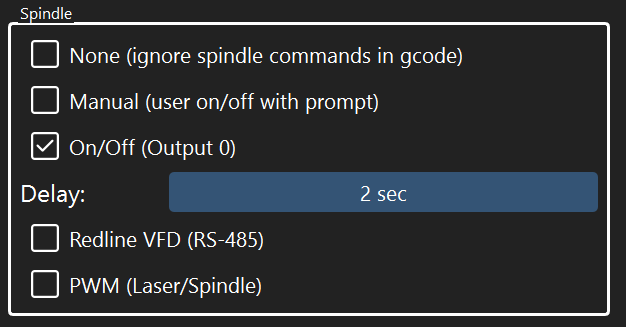
The Spindle setting group selects the active spindle.
| Spindle | Description |
|---|---|
| None | Spindle commands in toolpaths are ignored. |
| Manual | The user will be prompted to manually turn on/off the spindle |
| On/Off | Output 0 is used to turn on/off the spindle A delay can be set so the controller waits after switching on/off the spindle. |
| Redline VFD | The RS-485 interface is used to control a Redline VFD spindle |
| PWM | The PWM output is used to control a spindle or laser. See the PWM section for info on configuration. |
PWM
The PWM setting group configures the PWM output.
The frequency of the PWM output can be adjusted between 1 Hz and 10 kHz.
The Max Value setting controls the g-code S value which represents 100% duty cycle.
In the example above, S1000 indicates that a spindle speed of 1000 in a toolpath represents a 100% duty cycle output of the PWM signal. A value of S500 would set the PWM output to a 50% duty cycle.