Inputs and Outputs
The RTS-X series of controllers are equipped with standard inputs and outputs designed to satisfy a wide range of machine configurations and support future expansion.
RTS-1 Front Panel
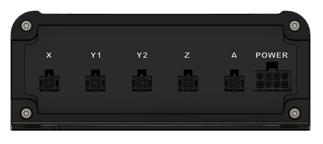
RTS-1 Motor Power Connector
The RTS-1 controller power input is an eight pin connector supporting an input voltage of 6-36V (48V available as special order).
CHECK POWER SUPPLY POLARITY
 Incorrect power supply polarity will damage the controller permanently.
| Manufacturer | Part Number | Image | Description |
|---|---|---|---|
| Molex | Mini-Fit Jr. 172488-0008 |
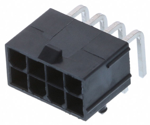 |
Motor connector header (controller side) |
| Molex | Mini-Fit Jr. 46992-0810 |
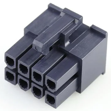 |
Motor connector mating plug (motor/cable side) |
Motor Power Connector Pinout
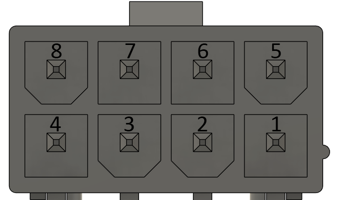
| Pin | Name | Description |
|---|---|---|
| 1 | GND | Motor power ground |
| 2 | GND | Motor power ground |
| 3 | GND | Motor power ground |
| 4 | GND | Motor power ground |
| 5 | VM+ | Motor power (positive) |
| 6 | VM+ | Motor power (positive) |
| 7 | VM+ | Motor power (positive) |
| 8 | VM+ | Motor power (positive) |
RTS-1 Motor Connectors
The RTS-1 Open Loop Controller has five motor connectors on its front panel. The controller supports up to five bipolar stepper motors including two Y-axis motors to support gantry-style CNC machines.
| Manufacturer | Part Number | Image | Description |
|---|---|---|---|
| Molex | 43045-0400 | 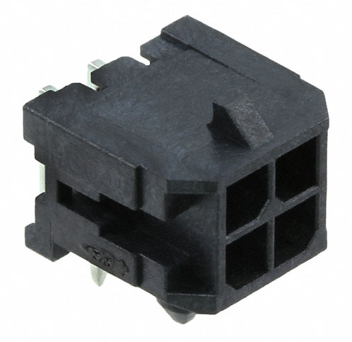 |
Motor connector header (controller side) |
| Molex | 43025-0400 | 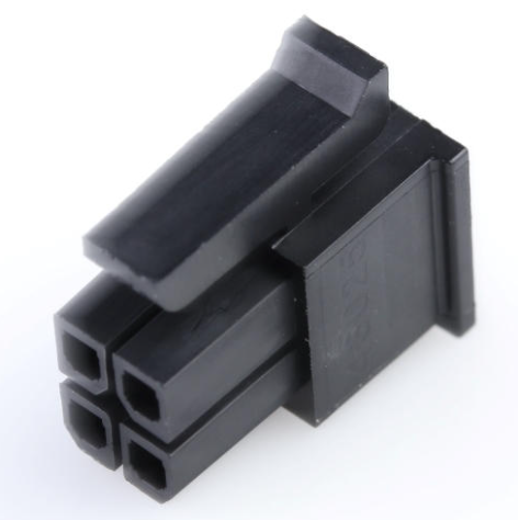 |
Motor connector mating plug (motor/cable side) |
RTS-1 Motor Connector Pinout
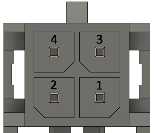
| Pin | Name | Description |
|---|---|---|
| 1 | B+ | Winding Phase B+ |
| 2 | A- | Winding Phase A- |
| 3 | B- | Winding Phase B- |
| 4 | A+ | Winding Phase A+ |
RTS-2 Front Panel
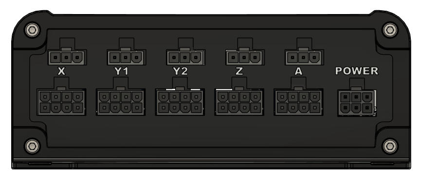
RTS-2 Motor Power Connector
The RTS-2 controller power input is an six pin connector supporting an input voltage of 6-36V (48V available as special order).
CHECK POWER SUPPLY POLARITY
Incorrect power supply polarity will damage the controller permanently.
| Manufacturer | Part Number | Image | Description |
|---|---|---|---|
| Molex | Mini-Fit Jr. 50362462 |
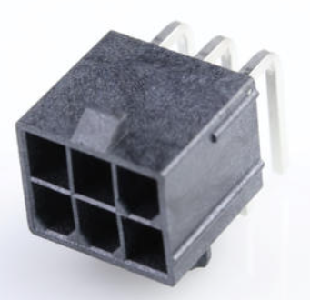 |
Motor power connector header (controller side) |
| Molex | Mini-Fit Jr. 39039062 |
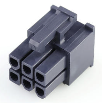 |
Motor power connector mating plug (power supply side) |
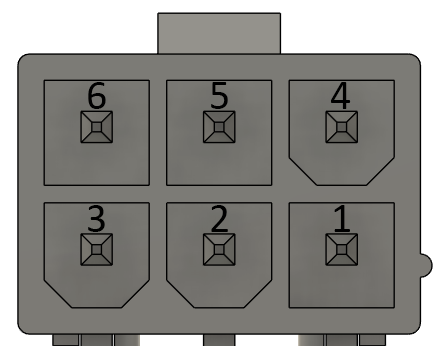
RTS-2 Motor Connector Pinout
| Pin | Name | Description |
|---|---|---|
| 1 | GND | Motor power ground |
| 2 | GND | Motor power ground |
| 3 | GND | Motor power ground |
| 4 | VM+ | Motor power (positive) |
| 5 | VM+ | Motor power (positive) |
| 6 | VM+ | Motor power (positive) |
RTS-2 Motor & Homing Sensor Connectors
The RTS-2 Closed Loop Controller has five motor connectors on its front panel. The controller supports up to five closed-loop stepper motors including two Y-axis motors to support gantry-style CNC machines. Each motor is paired with a three pin homing sensor connector.
| Manufacturer | Part Number | Image | Description |
|---|---|---|---|
| Molex | Mini-Fit Jr. 172488-0008 |
|
Motor connector header (controller side) |
| Molex | Mini-Fit Jr. 46992-0810 |
|
Motor connector mating plug (motor/cable side) |
| Molex | Mini-Fit Jr. 172648-0103 |
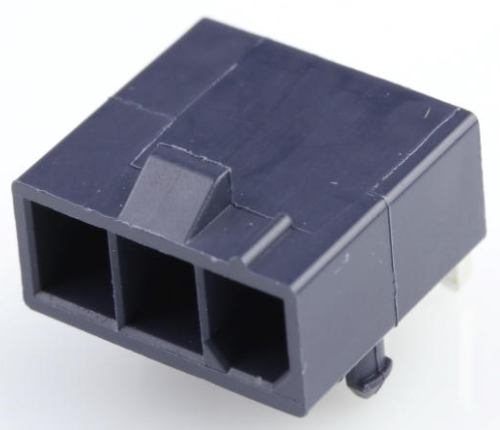 |
Homing sensor header (controller side) |
| Molex | Mini-Fit Jr. 50-29-1662 |
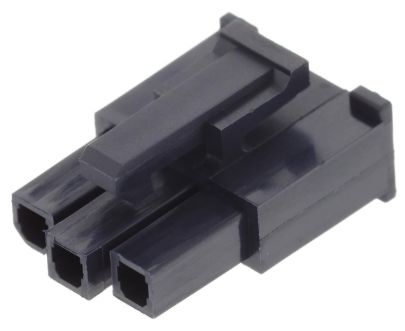 |
Homing sensor connector mating plug (motor/cable side) |
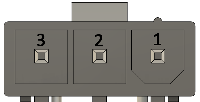
RTS-2 Homing Sensor Connector Pinout
| Pin | Name | Description |
|---|---|---|
| 1 | GND | Sensor Ground |
| 2 | 5V | Sensor Power Supply (10mA Max) |
| 3 | SW | Sensor Input (Switch, normally open) |
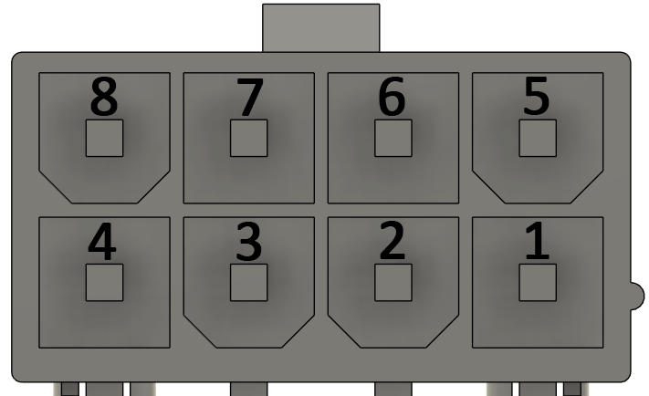
RTS-2 Motor Connector Pinout
| Pin | Name | Description |
|---|---|---|
| 1 | GND | Motor Ground |
| 2 | STEP+ | Motor Step Signal (positive) Differential output |
| 3 | DIR+ | Motor Direction Signal (positive) Differential output |
| 4 | EN | Motor Enable Output Signal |
| 5 | VM | Motor Power Supply |
| 6 | STEP- | Motor Step Signal (negative) Differential output |
| 7 | DIR- | Motor Direction Signal (negative) Differential output |
| 8 | FAULT | Motor Fault Input Signal Open collector from motor |
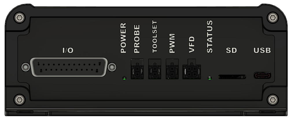
I/O Panel Layout
The I/O panel layout is common to the RTS-1 and RTS-2 controllers.
| Name | Description |
|---|---|
| I/O | DB-25 I/O Connector |
| POWER | Power LED |
| PROBE | Probe Input |
| TOOLSET | Tool Setter Input |
| PWM | Pulse-Width Modulation Output Laser/VFD |
| VFD | VFD Interface RS-485 |
| STATUS | Status LED |
| SD | SD Card Interface |
| USB | USB-C Host Interface |
DB-25 I/O Connector
The DB-25 connector contains the inputs, outputs, and RS-485 communication interface.

| Pin | Name | Description |
|---|---|---|
| 1 | Input 0 | Isolated input 0 |
| 2 | Input 1 | Isolated input 1 |
| 3 | Input 2 | Isolated input 2 |
| 4 | Input 3 | Isolated input 3 |
| 5 | Input 4 | Isolated input 4 |
| 6 | Input 5 | Isolated input 5 |
| 7 | Input 6 | Isolated input 6 |
| 8 | Input 7 | Isolated input 7 |
| 9 | Output 0- | Isolated output 0 negative |
| 10 | Output 0+ | Isolated output 0 positive |
| 11 | Output 1- | Isolated output 1 negative |
| 12 | Output 1+ | Isolated output 1 positive |
| 13 | Isolated Ground | Ground reference for inputs, probe, and PWM |
| 14 | RS-485 Ground | Non-isolated RS-485 ground reference |
| 15 | No connect | Future expansion, do not connect |
| 16 | No connect | Future expansion, do not connect |
| 17 | OUT3- | Isolated output 3 negative |
| 18 | OUT3+ | Isolated output 3 positive |
| 19 | OUT2- | Isolated output 2 negative |
| 20 | OUT2+ | Isolated output 2 positive |
| 21 | PWM | Isolated PWM output (5V) |
| 22 | Probe Input | Isolated probe input (switch) |
| 23 | RS-485+ (A) | VFD RS-485 communication interface |
| 24 | RS-485- (B) | VFD RS-485 communication interface |
| 25 | Isolated Ground | Ground reference for inputs, probe, and PWM |
Probe Input
| Pin | Name | Description |
|---|---|---|
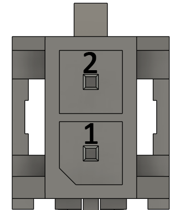
| 1 | PROBE | Probe Input |
| 2 | I/O GND | Isolated I/O Ground |
| Manufacturer | Part Number | Image | Description |
|---|---|---|---|
| Molex | 43045-0200 | 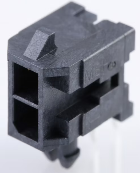 |
Probe connector header (controller side) |
| Molex | 43025-0200 | 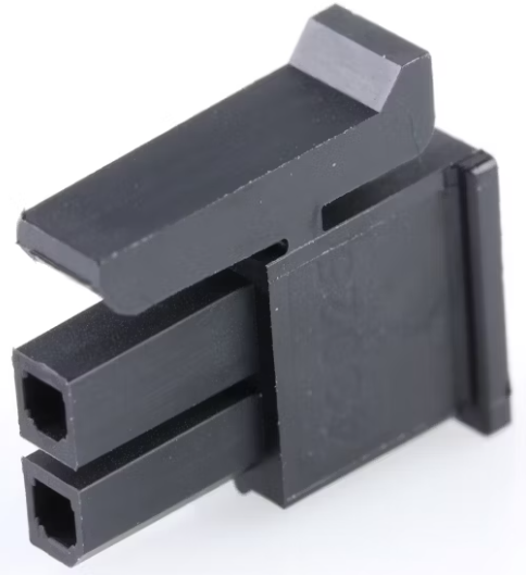 |
Probe connector mating plug (probe/cable side) |
Tool Setter Input
| Pin | Name | Description |
|---|---|---|
| 1 | TOOLSET | Tool Setter Input |
| 2 | I/O GND | Isolated I/O Ground |
| Manufacturer | Part Number | Image | Description |
|---|---|---|---|
| Molex | 43045-0200 | |
Tool Setter connector header (controller side) |
| Molex | 43025-0200 | |
Tool Setter connector mating plug (toolset/cable side) |
PWM Output
| Pin | Name | Description |
|---|---|---|
| 1 | PWM | Pulse-Width Modulation Output (5V) |
| 2 | I/O GND | Isolated I/O Ground |
| Manufacturer | Part Number | Image | Description |
|---|---|---|---|
| Molex | 43045-0200 | |
PWM connector header (controller side) |
| Molex | 43025-0200 | |
PWM connector mating plug (laser/cable side) |
VFD Interface
RS-485 Precautions
Do not exceed common-mode input voltage range of +12V to -7V
 Use twisted pair cable, shielded cable is preferred
Follow best practices for RS-485 grounding and common mode protection.
Refer to applicable machine & safety standards.
| Pin | Name | Description |
|---|---|---|
| 1 | RS-485 A | RS-485 Data+ |
| 2 | RS-485 B | RS-485 Data- |
| 3 | GND | RS-485 (non-isolated) |
| 4 | GND | RS-485 (non-isolated) |
| Manufacturer | Part Number | Image | Description |
|---|---|---|---|
| Molex | 43045-0400 | |
Motor connector header (controller side) |
| Molex | 43025-0400 | |
Motor connector mating plug (motor/cable side) |
Interfacing to GPIO
Inputs: General
DO NOT DRIVE INPUTS WITH EXTERNAL VOLTAGES
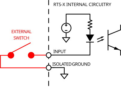
Inputs are intended to be connected to passive switches. Do not connect voltage sources to the inputs.
Eight GPIO digital inputs are available on the DB-25 connector. These inputs are optically isolated and reference to the isolated ground on pins 13 and 25.
The probe and tool setter inputs are also optically isolated and follow the same input circuit as the GPIO inputs.
The inputs are intended to be connected to switches. Connecting any input to the isolated ground will activate the input.
Outputs: General
OUTPUT MAXIMUM RATING
Outputs are intended for DC low voltage, low current output.
Do not exceed 50VDC/0.1A
Do not connect outputs directly to high voltage, high power loads. An external relay is required.

Four dry contact outputs are available on the DB-25 connector. Each output is an optically-isolated solid state relay and acts as a low-voltage switch.
Each output is rated for switching loads up to 50V (peak) with a maximum current of 100mA.
Refer to this article on how to connect an external relay to control heavy loads such as vacuums or cooling systems.
Outputs: Control
All four outputs can be manually controlled from the software using the I/O controls in the software.
Output 0 can also be controlled by M-code commands M3, M4 and M5 (spindle control) when the spindle is configured for "On/Off" mode. M3 and M4 will activate the output. M5 will deactivate the output.
Output 1 can also be controlled by M-code commands M8 and M9. M8 will activate output 1 and M9 will deactivate both outputs 1 and 2.
Output 2 can also be controlled by M-code commands M7 and M9. M7 will activate output 2 and M9 will deactivate both outputs 1 and 2.