Connecting an IoT Relay
NEVER connect RTS-X outputs to high voltage


Internet-of-Things (IoT) relays are a great way to control high power loads from the optically-isolated outputs on the RTS-X series of controllers. The lower power outputs on the controller can be used to activate and deactivate the outlets on the IoT relay.
Materials
The following materials are recommended to switch a high voltage load from a controller output:
-
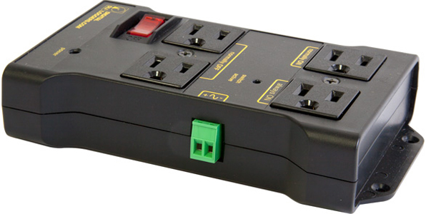
IoT Relay
- 5V compatible input
- Outputs rated for your target load
- Safety certified to your geographic region
- Example from Digital Loggers
-
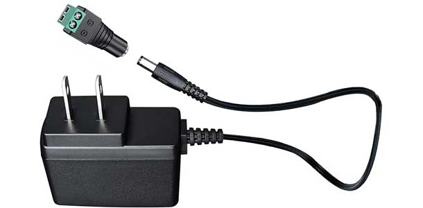
5V Power Supply
- 5VDC power supply
- Terminal block connector for easy wiring
-
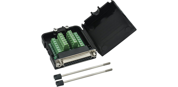
DB-25 Breakout Adapter
- Allows for easy connection and access to the outputs on the controller
- Provides terminal block connections for easy wiring
-

Wire
- 24 gauge wire for connections between the power supply and IoT relay control input
- Red and black for easy identification
Schematic
The outputs on a RTS-X controller act like a simple switch when activated. In order to drive an IoT relay control input, the output is used to switch the control voltage to the IoT relay. The schematic below illustrates the general concept.
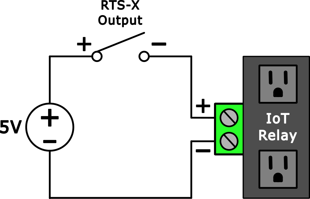
Wiring Example
The following step-by-step instructions will take you through wiring OUTPUT1 to control the IoT relay.
1. Prepare the IoT Relay and the Wall Adapter
Locate the wall adapter terminal block tip (left) that came with the 5V wall adapter.
Unplug the pluggable terminal block connector from the IoT relay. It can be helpful to mark the positive and negative terminals with a permanent marker.

2. Wire the Terminal Block Connectors
Connect the negative terminal of power supply terminal connector (left) to the negative terminal of the IoT relay terminal block (right). This connection is the blue wire in the photo below.
Cut a length of the two conductor black/red wire long enough to reach from the IoT relay to the RTS-X controller.
Connect the red wire to the positive terminal of the power supply terminal connector.
Connect the black wire to the positive terminal of the IoT terminal block.

3. Wire the Terminal Block Connectors
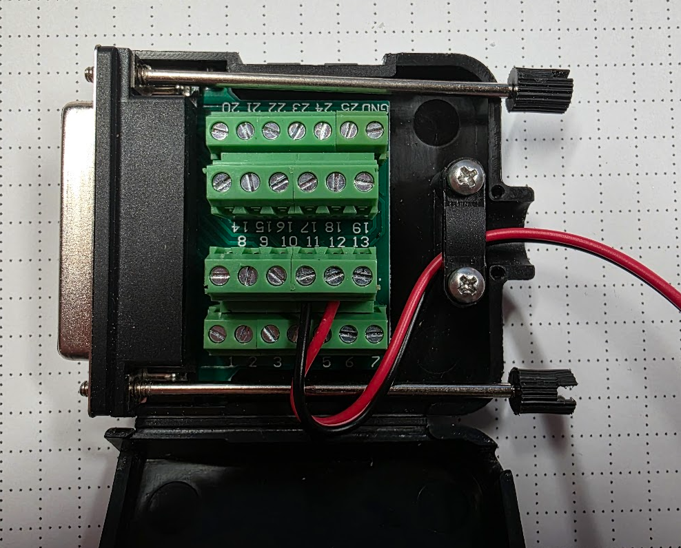
Locate the DB-25 breakout adapter and open the shell to expose the terminal block connections.
Connect the red wire to pin 12 (OUTPUT1+).
Connect the black wire to pin 13 (OUTPUT-).
4. Hooking Everything Up
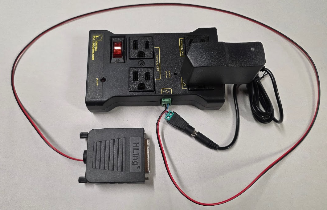
Locate the 5V wall adapter and plug it into the "Always On" plug of the IoT adapter.
Plug the pluggable terminal block back into the IoT relay.
Plug the barrel connector of the 5V wall adapter into the terminal block tip.
The completed setup is shown below.
5. Testing
Plug the AC line cord that came with the IoT relay into the relay and plug it into a wall outlet.
Plug the DB-25 terminal block adapter connector into the RTS-X controller.
Toggle OUTPUT1 on the controller and listen for the click of the relay.
A vacuum can now be connected to the "Normally OFF" outlet on the relay.
The vacuum can be turned on and off by toggling OUT1 from the user interface or using M8 & M9 gcodes.